Métis 2 Bobber Build

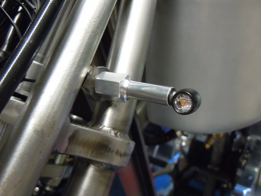
Got the front indicators mounted today. The mounting brackets need final welding & I'm not 100% sure that I'm happy with the stalk shape so I may have to make some revised versions at some point.
The Kellermann indicators are very small, only around 9mm diameter at their widest & around 13mm in length. They are very bright too :cool:
DSCN5166.webp
 
Ordered the speedo for my bobber the other day. The one I really wanted I can't get because the company who were going to build it for me had supply problems during covid & then when they were able to get the mechanisms they had doubled in price.
So, unless they can find a supplier in the future I'll use one of these Motogadget items. There are Smiths old style units available with electronic innards, but they don't have integral idiot lights & I didn't want to mount idiot lights somewhere. They seem well put together & I guessing/hoping because they are German made it will be reliable !
The cardboard cut-out is to see what it looked like, I'd have preferred a Smiths unit because they also don't come with such an optimistic top speed, there were options for 80mph or 120mph top speed & the needle started at the five-past position, which I though looked good. But, like I say, no integral idiot lights.

762263C4-1F86-48C9-A8D1-1AB0801098BA_1_105_c.webp
 
Following in Exi's footsteps, I've made a mounting bracket for my somewhat optimistic speedo over the last couple of days. Bent it up this morning & it seems to look ok. I just want to make an alloy case for it now, to mount the speedo in it & to attach the mounting bracket to. There are threaded holes in the back of the Motogadget unit to mount a bracket to, but I prefer it to have a case covering the back up & make it look a bit tidier.

1A1ED860-878B-4A87-A3E6-424EC936BF9C_1_201_a.jpeg


I doubt when the bike is running that it will ever get much over 70 mph, the other bike is happy around 55 ish & I expect that this one will be similar.

091B2589-A473-40F4-B6B9-7E028DA59BCD.jpeg


The unit has idiot lights, just above the digital display window, for neutral, oil pressure, high beam & indicators. I choise this unit because of this, I didn't want to have to mount separate idiots lights somewhere & the only other option, (that I liked) was from Puca Instruments, but he was having great trouble getting hold of the movements during covid & then his supplier hiked the price up to make them un-economic to produce. The other beauty of the Puca option was that you could customise the clock face. Shame, but maybe at some point in the future he will be able to make some more & swopping over would be a quite simple job.
 
Last edited:
That’s the same one I used, the row of lights between 20 and 180 are the idiot lights

The cardboard cut-out is to see what it looked like, I'd have preferred a Smiths unit because they also don't come with such an optimistic top speed, there were options for 80mph or 120mph top speed & the needle started at the five-past position, which I though looked good. But, like I say, no integral idiot lights.
 
Started making a housing for my speedo, there are tapped holes in the back of the case to mount a bracket to, but I wasn't happy with that 'look".
So I bought a lump of alloy & started turning. I'm going to use the three tapped holes in the existing case to secure the speedo into the new case, but not sure how I'm going to counterbore the holes to sink the screw heads into yet. I need access to a milling machine, but my mate who I would normally have gone to is no longer with us so I will most likely go to a local engineering company, who I get to do my CNC machining. Hopefully they will be able to help.🤞

First job was to face-off one end & mark the position of the three mounting holes. A test fit for alignment seems to have gone well considering, albeit the screws were slightly tight, but I can open out the holes a bit to help once I know the speedo fits in the new housing. Because the cable coming out from the rear of the speedo can't be disconnected I can't fully get the speedo in position until I've drilled the hole for the cable to exit the new housing.
3A48B4BE-1F37-46D7-8801-AA9B1B96BBA3_1_105_c.webp


First stage of boring is now done, just need to bore out the bottom a bit more for the cable & gland to clear. I'll drill the cable hole while the job is on the lathe as it is held firmly in place at the moment. If I wait until it's off the lathe I'll have the problem of holding the case firmly while I drill it, without marking the outside of the case or ripping fingers off if the drill grabs ! 🤢
33F689E2-78F5-4E13-9375-ECCE923E9FAE.webp
 
I've now got the basic shape for the speedo case done, just needs a bit of prettying up somehow ! Might put some shallow grooves in it around the main body depending upon where I can get it held in my chuck. The top section is quite thin walled so don't want to distort that area as the speedo won't fit then !!
0BEB33AA-8E53-4160-95FE-7FF271C050F9.webp


Also, the three mounting holes need counter-boring to hide the cap head screws. I was also going to make the cable exit hole come out at a bit of an angle, but when I offered it up into place the cable looked better coming out from the centre of the case, so I drilled that hole too. I'll have to open it up a bit to suit the grommet, which I haven't got yet, but it'll do for the time being. At least I could test fit the speedo & make sure the mounting holes were in the correct position, I did open them up slightly just to be sure.
B248C8E1-2D18-44C7-AF49-8274266E8B81.webp

780678E9-42D6-45D8-BDE7-F9B27EC2D61E.webp
 
I've now counterbored the three speedo securing holes & drilled a small drain hole at the lowest point, just-in-case !
I also put a couple of grooves in the main body to hopefully get rid of the blandness.
553D4430-1A5E-47EE-9CA8-8C0AD1E10F3F.webp

7F0C942C-ADC8-4DE6-B1CE-3E17C9551547.webp


All that's left now to do is to open out the cable hole once the grommets arrive this coming week & drill & tap the two mounting holes in the case once I've bent the mounting bracket to follow the contour of the case. My friendly engineering company are just milling out a bit of square steel bar with the correct radius in. Once I have that I can put it in my press & bend it up to suit.
 
Picked up my gearbox mounting plate today, that I got a mate to draw & had made at a local sheet metal shop I use. I originally asked him to draw three versions, one with 4mm off-set, one with 5mm off-set & one with 6mm off-set, these would allow me to hopefully get the correct rear wheel/gearbox alignment. Anyway my mate was a bit clever & drew one bracket with slotted holes that would cover all three of my options, plus anything inbetween.
DSCN5342.webp

DSCN5344.webp


So, perfect alignment has been achieved, chain shortened & riveted up. Another job to tick off the ever growing list. I don't know what it is with "projects", but you do one job & it seems to create three or four other jobs !! :ROFLMAO:
Maybe that's why it taking Exi so long to finish his "project" !! :ROFLMAO:
 
Picked up my gearbox mounting plate today, that I got a mate to draw & had made at a local sheet metal shop I use. I originally asked him to draw three versions, one with 4mm off-set, one with 5mm off-set & one with 6mm off-set, these would allow me to hopefully get the correct rear wheel/gearbox alignment. Anyway my mate was a bit clever & drew one bracket with slotted holes that would cover all three of my options, plus anything inbetween.
View attachment 81947
View attachment 81948

So, perfect alignment has been achieved, chain shortened & riveted up. Another job to tick off the ever growing list. I don't know what it is with "projects", but you do one job & it seems to create three or four other jobs !! :ROFLMAO:
Maybe that's why it taking Exi so long to finish his "project" !! :ROFLMAO:
I do a job and take a month or two off (and sometimes 4 or 5 years) - must owe me about 400 hours in all if I tot them up whereas mere mortals would take years :oops:
 
Another wet day in the North-west has confined me to the garage, I could have done a bit on our ensuite, which is next door to the garage, but the garage won ! ;)

Made a stand-off to mount the tax disc holder, not that the bike needs it legally, but it would have had one in the era it's modelled on so it has got one ! I'll get a "period" replica tax disc made at some point.
E0BF7AE4-E55A-454C-9556-31A38F578461_1_105_c.webp


Then I moved on to tacking up the rear chain guard mount, I'd made the individual parts a while ago. This proved a bit fiddly as there's not much clearance between the chain & the nut I'd made to hold the chain guard to the actual bracket. Anyway, it's now ready for my mate to do the finish welding.
A18B4F0A-2CCC-489E-982E-356430288E58.webp

8C9625C9-371B-4306-A4B3-2B0E4E93F299.webp
 
I can't wait to see this project in it's completion, it's going to be one fab moto.
 
Managed to get the speedo bracket bent up today so that's now mounted.
86AFE475-19F3-4FBF-8B77-C57B2DB6A7AB.webp

I made a couple of 1mm thick, plastic washers, just to keep the alloy housing & steel mounting bracket from fretting against each other once the motor is in & running. Yes they do vibrate a bit so the screws will be thread locked too, as will ALL nuts & bolts, or wire-locked, or both in the case of the rear sprocket & engine drive pulley !! :ROFLMAO:

Also got the final parts made for the chain guard front mount so tomorrow I'll tack that in place. Once that's done it's ready to go & get the rear mudguard, the under-seat cover & headstock cover made. That's booked in for September (y)
8B2F74D0-3CA4-44B8-A1E6-489FBB9DA664.webp

76CF56E7-3582-4948-BA21-CB9AD3E5CB7F.webp

02E157E4-C7F5-4A85-931C-A1AE289F5BDD.webp

It would have been nice if the chain guard butted up to the back of the primary drive plate instead of leaving that big gap. But, in my defence I had two of these chain guards made when I built the first bike, which is obviously slightly different frame wise to this build. Anyway, I can always make/get made something to fill that gap at a later date.

 
Managed to get the speedo bracket bent up today so that's now mounted.
View attachment 83344
I made a couple of 1mm thick, plastic washers, just to keep the alloy housing & steel mounting bracket from fretting against each other once the motor is in & running. Yes they do vibrate a bit so the screws will be thread locked too, as will ALL nuts & bolts, or wire-locked, or both in the case of the rear sprocket & engine drive pulley !! :ROFLMAO:

Also got the final parts made for the chain guard front mount so tomorrow I'll tack that in place. Once that's done it's ready to go & get the rear mudguard, the under-seat cover & headstock cover made. That's booked in for September (y)
View attachment 83345
View attachment 83346
View attachment 83347
It would have been nice if the chain guard butted up to the back of the primary drive plate instead of leaving that big gap. But, in my defence I had two of these chain guards made when I built the first bike, which is obviously slightly different frame wise to this build. Anyway, I can always make/get made something to fill that gap at a later date.

Where did you get your inspiration from for the bracket :love:


SQUARE_46f63670-d6e6-4323-8b18-7754f49a7338.webp
 
I'll just drop this in here too :whistle:


I don't know, you try & help a guy with the benefit of your experiance & all he does is riducule one little bracket :rolleyes: I thought is was quite nicely executed to be honest, it took me ages to file it to shape ! :ROFLMAO:
Plus, I have plans to get the bike on the road & use it, sooner rather than later, or much later in Exi's case going off current progress, (his thread is now mahoosiff & spans more than one decade) :LOL:
I am wondering if he's just posting on my thread just to build my reply tally up ? :unsure:

Ditto :ROFLMAO: but the bracket is a bit poo (not the bracket itself but the overall execution and application :))

You didn't answer if you had copied my posh pipe clips with cheap unbranded ones 👀

.
 
Got my stiffening metalwork tacked in place on the oil tank/battery box now, ready for final welding. It just adds some strength to the oil tank & battery box where they join & neatens that area up.
418F26C5-D4B5-4531-9B38-F8BEE9A28C05_1_201_a.webp

91F4D28C-5AE4-4805-91A5-C60111ECAB24.webp

B790318C-969C-4FCF-8608-5756820D8ED5_1_201_a.webp

Once that welding is done all I need to do is mount the ignition switch & work out where a Motogadget box can go. I can't decide yet whether to try & get it in the battery box or in-between the two fuel tanks. I'll have to take the battery off the other bike & have a weigh up of my options, (I'll be using the same size Shorai lithium ion battery).
 
I was going to get Métis 1 out today & take it to the Stockport Motorcycle Show, but as usual the weather is shit so I had a brew in my new mug while I contemplated cable routing at the front of Métis 2 ! :)
D7CBB68E-4BF7-4423-A652-354175C84874.webp


I'm using a replica Springer style headlight & apart from having an odd-ball bulb fitting, P15D, connections to the bulb are made via a plastic block in the bottom of the headlight shell. I want to make all the connections at the front of the bike in the headlight shell like I did on the other bike & this requires the removal of this block & fitting a grommet in the hole that's left.
BD0D55D9-7C76-428A-B700-5176AF943D92.webp

After drilling out the rivets the block is out, grommet fitted & the hole in the fixing plate opened out to suit. The small hole at the back of the shell, where the fixing plate mounts is the original earth point for the headlight. I've opened out that hole too so I can use it to route the speedo cable though it, via a grommet of course. It makes the cable route for the speedo cable much neater than dropping down & then back up to go though the grommet in the bottom of the shell.
BF9C1E2C-1709-4296-9716-884C383AF636_1_201_a.webp


I'll just drop this in here too :whistle:


Ditto :ROFLMAO: but the bracket is a bit poo (not the bracket itself but the overall execution and application :))

You didn't answer if you had copied my posh pipe clips with cheap unbranded ones 👀

.
I didn't copy your use of cheap shit hose clips Exi, I chose to use some posh ones instead. 17.5mm versions though ! :ROFLMAO:
F63223C0-D2B0-4534-8DA5-299FED4C47C6.webp
 
I didn't copy your use of quality hose clips Exi, I chose to use some Chinese ones instead as my build is so slow I could wait for the boat to deliver them! :ROFLMAO:

'Corrected' for you - and why are all your bolts too long - get a grip man, it's all in the detail :) (y)
 
Back
Top Bottom