Scope Creep (Bimota DB2 2v 944 and custom ECU)

hindsight

Well-known member
As encouraged in another thread, I'll start posting some (largely historic now) detail on the recent bit of work that I did to my Bimota DB2SR. Most of this content I had already written and posted on the Bimota forum, but I'll review/update and repost some of it here, as others may find it interesting, and it may spark off some interesting conversations.

I've had several carbie 900SS's in the past, and back in 2018 or so, I was looking at a couple of Superlight's (well, who doesn't fancy a superlight, really?). Then, after half a bottle of wine one evening (well, it was probably nearer a full bottle, if I were to be honest), I figured that the DB2 was really the ultimate "Superlight" type machine, and the DB2 was certainly something that I'd lusted after for some time.

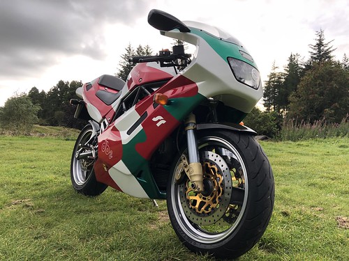
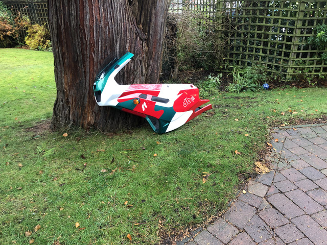
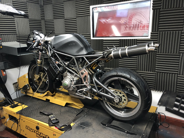
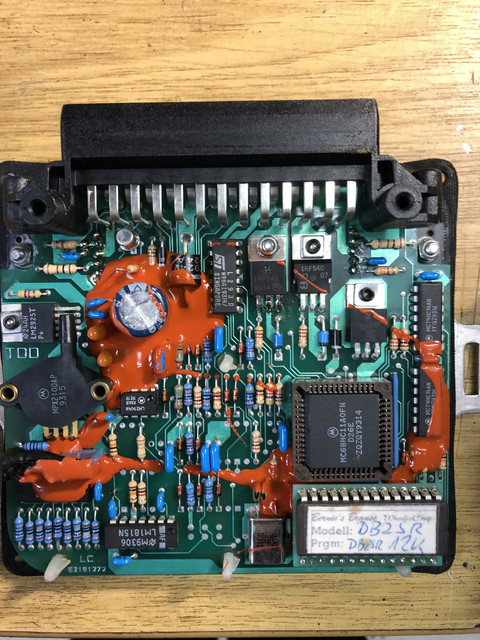
A few months later, and I'd purchased a DB2 from a nice fella in Wales (Hi Ralph, I suspect you'll stumble across this thread at some point). In fact - not just a normal DB2, but a DB2SR - which is the super-rare fuel injected version (most DB2's are carbie, but if the DB2 isn't rare enough as it is, a small handful of them had a custom FI system fitted at factory) in a lovely tricolore paint scheme.

48607980932_8831f8aca7.jpg


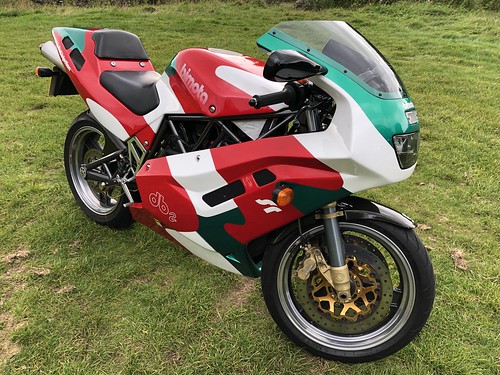
In 2019 I took it on a lap of Scotland with some friends, and it was an absolute joy to ride. It weighs about as much as a well loaded cheese sandwich, and handles beautifully. I also had my 2015 Triumph Tiger 800 with me on that trip (a friend was riding it), and we swapped about - it was interesting that the ageing DB2 could still outperform the modern bike on nearly every parameter.

48607469438_91bbb45124.jpg


Later in 2019, in a fit of stupidity, I very nearly sold this bike - I'd advertised it, and even had contact from several people who were interested in purchasing, even internationally. To be fair, the reason I was considering selling was to fund the purchase of an RC45, but in a conversation that I still can't quite believe - SWMBO convinced me to keep the Bimota. As it turned out, I also walked away from the RC45 in a separate unrelated decision, but that's off topic.

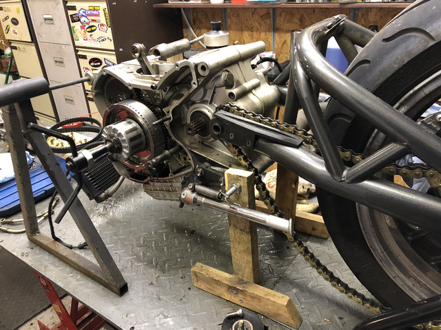
So the DB2SR was to stay. Over the winter (November 2019) I lined up a service - nothing particularly special, just a set of belts (from Exige, thanks Stu), oil, clearances - the usual stuff. It doesn't get run hard, and doesn't get a lot of miles, so I wasn't planning on doing a lot of work on it, but it didn't exactly work out like that...

After stripping the bodywork off, and starting the service, I figured I would just pop the horizontal head off, just to check whether it still had the original bore size. As I measured the 92mm bore (904cc), a glimmer of an idea started to emerge, which soon escalated into what probably is my worst (best?) example of bike project scope creep so far..

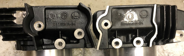
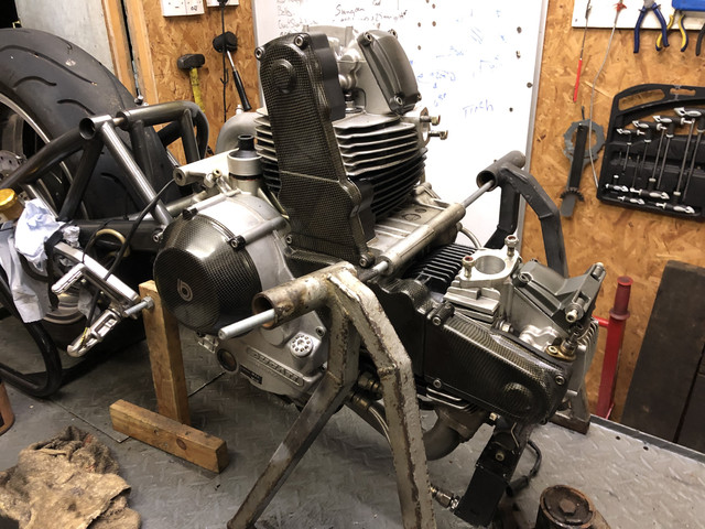
So the initial plan was to carry out a ST2/944 barrel/piston upgrade. I took a set of 94mm ST2 (water cooled) barrels and arranged for the necessary engineering work to convert them appropriately to be oil/aircooled. Essentially the trick here is to drill through the jacket into the coolant gallery, then weld up the hole in the jacket. The flanges on the barrels (previous used for coolant on the ST2) are then changed for the 900ss oil flanges, and the oil will then flood the jacket, and as a benefit it should giving greater cooling capability than the standard 900ss barrels which seem to use galleries for cooling, rather than a fully flooded jacket.

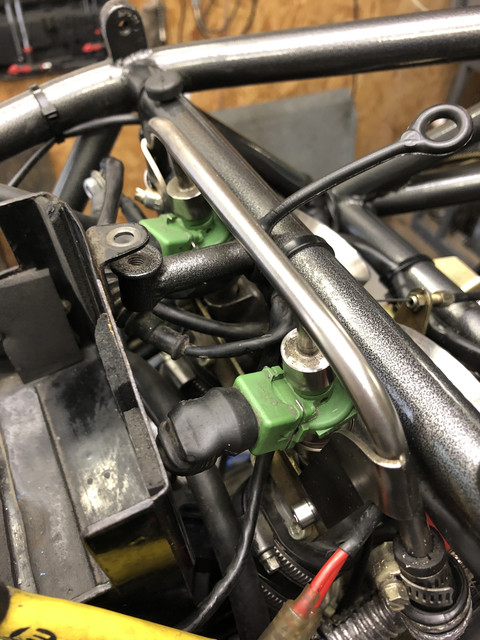
As I have no welding skills, the welding job wasn't done by me - so I explained to a professional what was required, and the job was done very tidily indeed. My contribution was a dab of black hammerite, and the job is almost invisible, aside from the missing fins that you can see on the left-hand barrel that was necessary to be machined to gain access. Virtually none of this is visible once the bike is back together though.
IMG-1022.jpg


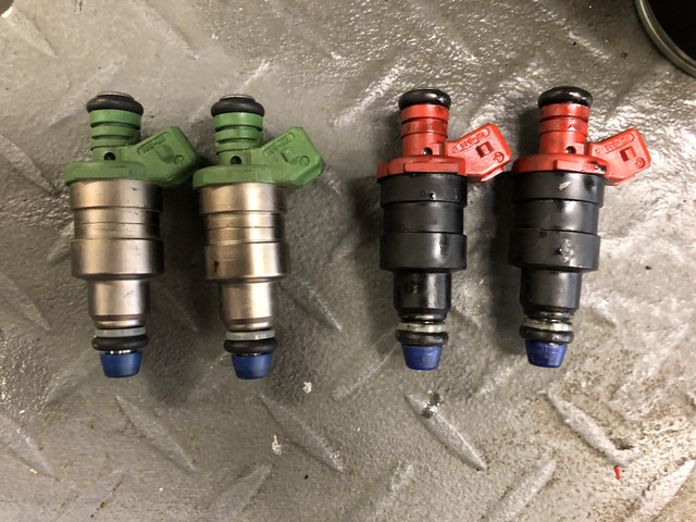
There's also a couple of holes in the top of the barrels that need to be blocked off with core plugs. In the below pic - the top pair of barrels are ST2, with blue and red markings of the changes that were midway through being made, and the bottom pair are the original DB2/900ss units.
IMG-1021.jpg


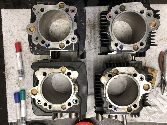
Using the 94mm ST2 barrels is a nice way of doing a big bore conversation, because it leaves plenty of material on the cylinder wall, if I should choose to get them further bored to a larger capacity, and the additional oil cooling available to them should allow that (it also means that I've got the original 92mm/904cc barrels/pistons, should anything ever go wrong..). I could certainly go to 96mm/984cc in the future, and I suspect that 98mm/1068cc might be possible, but that would probably be pushing it a bit far...

The disadvantage of what I've done of course is that the pistons aren't particularly high-compression - but I could easily replace the pistons in the future, if that became a priority, and indeed, if I ever go to 96mm, then I'll need new pistons anyway...[self warning: potential for more scope creep...]

More to come in due course..
 
Last edited:
As I had the top end in pieces, it was obviously a good opportunity to take care of a few other things.

First, I'd noticed during disassembly that the cylinder head studs were of the old shiny/snappy variety, so, particularly given the 944 conversion, it was important to swap them out for the appropriate updated ones as a matter of course.

Next up was replacing the standard (HT) cams with "hot" HZ cams from another ST2. I believe these HZ ducati cams are identical to the aftermarket Vee-two 210 cams, which were a popular performance upgrade back in the day. They give increased duration and higher lift on the exhaust. The following figures are from Brad Black http://www.bikeboy.org/duccamspec.html

1607858821988.png


Because I had swapped the cams, it soon became clear that every valve clearance was out. Normally I'd be doing this myself, but with so many shim adjustments required, as I don't have a shim set it made sense to outsource the shimming of the heads (to Eddie Stone at ERS in Fife, who also simultaneously arranged the engineering work for the barrel conversations mentioned previously).

I'd also noticed during disassembly just how heavy the stock exhaust is - which is surprising given how light the bike is overall. Unfortunately DB2 exhausts aren't exactly "off-the-shelf" stock items for most places, So, after some research, I'd been pointed in the direction of Yahoo Japan auction site, very much like Ebay, but in err, well, Japanese. Indeed there was a carbon fibre race system listed - fairly pricey, but definitely workable. Of course, when my bid was accepted, I hadn't really thought too much about the packaging and delivery costs, and neither had I really thought much about the import costs (I knew there would be costs, I just didn't want to think about it).. so by the time I received it - this exhaust system was wincingly pricey unfortunately. However - particularly given that it is half the weight of the original, it'll be worth it in the end..

IMG-0928.jpg


Meanwhile, I had also dropped the bodywork off to a local paintshop, as the fairing had a little damage that could usefully fixed, it didn't look *bad*, just that it could probably be improved. Offloading the bodywork to the paintshop was also a bit of an advantage because storing the DB2 bodywork is a right nuisance when it's not on the bike, as the top and front fairings are one-piece units (and consequently also a PITA to remove and install..)
IMG-0875.jpg


As the various parts started to come back over the following months I was able to start reassembly, and it was good to see the engine come back together. I used the opportunity for my 15-year-old son to help build it, and took time to explain the mechanics of it, and also set him mathematical challenges based on what we were doing to try and illustrate the application of some of his school lessons.

In the following picture, note the flywheel with the drillings around the circumference - this is the 60-2 missing tooth timing signal picked up by the normal flywheel pickup that the Bimota ECU uses for timing information, and is specific to the DB2SR (it's a normal steel Ducati flywheel that has been machined with those timing marks). It also meant that I couldn't put a super-lightweight flywheel on unfortunately, without arranging for an identical set of timing marks to be put on it, so I quickly abandoned that idea and had to return the super lightweight flywheel that I had purchased to Kaemna when I figured that out.

IMG-0900.jpg

IMG-1035.jpg


It sounded rather nice before with the stock exhaust on, but once all assembled, with the new exhaust on, it sounded quite fruity indeed. Not quite into 888/ASBO territory, but not far off either.


All the while through this, I was aware that the ECU was set for the standard exhaust and 92mm/904cc and been pondering how I was going to adjust the fuelling for all the changes, and indeed, if I were to consider a further upgrade to 96mm/984cc in the future, how would I do that also?
 
Last edited:
If you ever get stuck with exhausts again back in the day the Galleria Bimota used Mark Hill at MHP exhausts for their exhaust manfacturer of choice, he should be able to help out if you ever need it. He's sorting out the refurnishing of my 900ss Spaghetti system as we speak.
 
The bike ran reasonably well with the engine updates on the original ECU, but a trip to the local Dyno shop clarified that the fuelling really ought to be adjusted. It was running much too lean up to 6000rpm, then running rich afterwards.

IMG-1063.jpg


So, let's talk about the ECU - it's not Marelli, like Ducs of a similar vintage - but TDD, a small Italian company, based not far from the Ducati factory in Bologna. It seems to be an earlier version of the ECU in use by the Bimota V-Due, and also seems to be in common use for Italian rally cars. Needless to say though, I couldn't find any documentation (Bimota or otherwise).

I had been considering the use of a Power Commander. Such a piggyback device could undoubtedly do the job - it sits between the ECU and the injectors, and can extend or reduce the electrical pulse going to the injector, changing the fuelling. While there isn't a PC specifically for the Bimota, as long as the connectors are compatible, then it would work. To me, at that time, that kinda felt like cheating though - I'd much rather have an updated EPROM. Looking back, I do wonder if this was the right decision, as this could have avoided a *lot* of work, but then, it has been a very interesting journey, so I have no regrets.

Popping the ECU open revealed that it had an EPROM, similar to P7/P8 ECUs, which was potentially useful. I can do EPROM.

IMG-0882.jpg


This particular EPROM was fitted with an encryption/scrambler device on it, intended as copy protection. I had hoped that if I could read the EPROM image, then perhaps I'd be able to find the fuel map within the image using TunerPro software. I used two methods of circumventing the copy protection mechanism, hoping that the results from the two methods correlate, but unfortunately that resulted in two different images, neither of which had an obvious fuel map.

The EPROM didn't look OEM - it had a label on it that suggested it to be aftermarket, and I eventually stumbled across Bernhard Bludau's website ( Bimota Chip-Tuning , BBPowerchip, Chip Tuning, Eprom ). After swapping a few emails - it turned out that he was the last person to tune this bike, twenty-two years previously. He provided some very useful advice and guidance. He also suggested that he'd be able to provide a 944 EPROM. Super - I thought this was going to be easy.

That was around about March 2020, when the whole C19 thing was kicking off in a bad way, and Europe was going into lockdown. Unfortunately I saw no further replies from Bernhard.

Meanwhile, I had also been starting to think about and research building a new ECU - one that was open and would run modern software, allowing everything to be fully tuned. I wondered about building a plug-and-play replacement ECU that didn't require any modifications to the bike. With lockdown starting, it was clear that I'd have a bit more spare time over the coming weeks.
 
Last edited:
Unsurprisingly, there is no easily available wiring diagram for the DB2SR - one exists for the DB2, but that lacks all the important electrical stuff for the fuel injection, so I spent some time investigating and documenting the loom of the bike - every single sensor, cable and connection had to be traced accounted for an understood - I particularly had to understand how each wire interacted with the 25-pin ECU connector, what it was used for, and how it worked.

It took a while, but I got there in the end, and that allowed me to build the first prototype

IMG-1158.jpg


IMG-1153.jpg


That first prototype wasn't particularly robust - but it proved a point and allowed me to improve the design over a few iterations - it had full functionality, allowing the engine to run. It can also connect to a laptop by either USB or bluetooth, which allowed me to visualise what it's doing, which has been tremendously helpful as I've been configuring it. Initially it was just running a base fuel and ignition map.


The circuit board pictured is a specialist unit, built specifically for the purpose of designing custom ECUs. My goal was to develop the idea, such that a £10 Arduino microcontroller could do the same job.

Once I was happy that the prototype was doing what I expected, then I set about designing a more robust PCB, which I ordered to be manufactured in China. I ordered the PCB with the small number of surface-mount components that I required installed, which meant that when it arrived, all I had to do was solder in place the loom connector, transistors and headers for the external components.

IMG-0017.jpg


Keen to test it without actually installing it onto the bike, I built (and wrote the software for) a test harness to allow me to simulate a 60-2 pulse from a flywheel at varying RPM. The photo shows a spaghetti of wires, but I'd later develop that with a loom and the correct connector to neatly connect to the ECU. You can see on the oscilloscope screen the generated/simulated CPS pulse, and the two ignition pulses that are being generated by the ECU, 90 degrees apart.

Frame-1.jpg


I was also doing a lot of thinking about the fuel map, and courtesy of Brad Black, I'd obtained a spreadsheet with the fuel map for a standard ST2, which seemed like a good place to start. However - when working through some of the maths, I'd spotted a problem.

The DB2SR runs Weber IW-042 (red) fuel injectors (which I believe the 907ie also uses), rated at 200cc/min.
The ST2 (and 888/900SSie/750SSie) runs Weber IW-031 (green) injectors, at 270cc/min.

If I take the fuel map for the ST2 and scale the injector duration up to compensate for the reduced flow on the IW-042's, then it becomes clear that the injectors quickly run out of time within an engine cycle, particularly at large throttle openings and high revs.

I suspect the flow could well have been a constraint at high revs/high throttle, even at 904cc. Glad that I figured that out on paper before starting to more fully explore the tuning, there was nothing else for it, but to install some greens..

IMG-0058.jpg


IMG-0059.jpg


I also received a present from a friend that had been playing with his 3d-printer..

749577a6-bd0b-4ec9-ae3c-c71b8397e911.jpg


I was so impressed by it, that only a few weeks later I bought myself a 3d printer also.
 
Last edited:
Buoyed by the positive progress overall, I proceeded to design and order an updated PCB: as previously mentioned, the goal was to have a board based on a standard inexpensive Arduino microcontroller, rather than the specialist EFI microcontroller that the previous two versions were built using. This brought a number of complexities as it required more circuitry and components on the PCB. Here it is -

4817-D2-A1-C3-DD-454-D-B71-F-BF7060-BAB7-D9.jpg


.. but I also added another feature - in order to explore the fuel tuning further, I'd decided to add a wideband O2 sensor. I'd arranged the new ECU board such that it presents O2 sensor connections on the pre-existing ECU diagnostic plug that is installed on the DB2 loom. The original ECU uses this connector for RS232 communications to a diagnostic device, and because the new ECU has both USB and Bluetooth, there is no real need for a dedicated diagnostic connector - so I figured that I may as well do something useful with it!.

I had a bung welded into the horizontal downpipe in a convenient but inobtrusive location, and once calibrated - the ECU can now measure the O2 content in the exhaust gasses.

2-D8-EECB7-8286-4-A6-B-9-DA0-690-F326-BF536.jpg
A6-EFBC4-C-E589-4035-B05-A-1-D51004225-D6.jpg


IMG-0060.jpg


This can be used for a number of things - firstly, for datalogging and manual tuning - understanding whether it's running rich or lean, then making manual changes to the fuelling, but it can also potentially auto-tune itself.

Meanwhile - I'd been thinking more about the ignition map, and that harness that I'd built to test the homebrew ECU. The test harness made use of a microcontroller to generate the simulated CPS signal, but I figured that it would be interesting if I could use that same microcontroller to measure the outputs (rather than using an oscilloscope), including the timing of the ignition and the duration of the injector pulse, whilst also being able to control the TPS and CPS signals..

IMG-0105.jpg


This allowed a full test of the new ECU, but I also realised that the same technique could be used to measure the ignition curve from the original Bimota ECU. Here's an example of the results - the ignition curve from the OEM ECU measuring the angle before Top Dead Centre (BTDC) of the horizontal ignition across the whole rev range, at 50% TPS.

curve.png

Interesting to note the timing retard and flatten at >8000rpm. That looks like a soft limiter, and I'll set the new ECU similarly.

I'll skip the detail of how this actually works, but at each of the TPS/RPM combinations of interest I took 200 measurements, eliminated any obvious outliers that would have been instrumentation errors, then averaged the results. That chart was constructed by interrogating each and every RPM between 1000rpm and 8500rpm to show a smooth curve.

Back onto the bike though - I've been chasing a few problems.. firstly, it had recently been idling way too high when fully warmed up (3500rpm or thereabouts). I had hoped that the new ignition table might help with this, because I could have sworn that the OEM ecu didn't have a high idle. However - after an amount of headscratching, I figured out that I made an obvious rookie error - I had been adjusting the throttle stop a few weeks previously, and I must have adjusted the balance screw, meaning that one cylinder was pulling way more air than the other, and there was too much air getting in overall. Dammit!, so out with the vacuum gauge, confirmed the issue and rebalanced the throttle bodies set the throttle stop and recalibrated the TPS. Once done, and I also adjusted the fuel map according to the O2 sensor, I got a beautifully stable 1150-1250rpm idle. Lovely.

The second issue was worse though, and more than once in I came close to giving up on this whole exercise. Since starting to try and tune the fuelling, occasionally, the bike would misfire (usually loudly in the throttle body) and stall. The ECU seemed to suggest that it was losing sync with the crankshaft sensor (which is a pretty terminal situation for timing accuracy..). I hooked the oscilloscope up, to have a look at the signalling from the crankshaft sensor and into the ECU - which was mostly clean, but there were some small isolated pockets of electrical noise (which could have been caused by the scope itself).


In the scope image above, the blue line is the output of the crank sensor (remember the picture of the flywheel? - the holes drilled into the flywheel generates that sine wave), and the yellow line is the square-wave input that the ECU uses - you can see small pockets of noise on each.

In any case, I figured that I could adjust the wiring to further separate the HT leads from the crank signal wire, and also revert the ECU to bluetooth comms (as I was using a USB cable, which *could* have been the source of interference). Things seemed to be a little better, but it was still stalling out, particularly when the throttle was increased.

I wasn't sure if the sync loss was cause or effect, or indeed whether that noise was causal or coincidental. Now - one of the things that really appeals to my inner nerd here is the amount of data available. I started studying the ECU performance logs in detail.. Here's an example of just some of the relevant metrics here:

Yellow=Air Fuel Ratio (from O2 sensor)
White=RPM
Green=TPS
Red=Sync loss counter (increments each time that a sync loss happens)

stall.png


The horizontal (x) axis is time, showing one of those stall events. You can clearly see the TPS (in green) rising to 33% when I blipped the throttle, and shortly after, the RPM signal (in white) drops off after the misfire and the engine stalls, but what was particularly interesting was the sequence of events. The sync loss (red line rising) was detected after the RPM dropped off - in fact, it was about 250 milliseconds after, which (at the initial 1500rpm) represents about six rotations of the crank (not accounting for the deceleration of the crank, so probably less than six).. It's starting sound very much like the sync loss was probably a consequence of the event, and most probably the crank coming to a halt (which would surprise the ECU when it stopped receiving positioning signals).

What then caught my eye was the AFR (Air Fuel Ratio), which goes incredibly lean… and bearing in mind that there is always a small delay to the AFR reading arriving at the ECU from an event happening - could it have been the cause of the misfire and ultimately the stall?

It was interesting starting to understand the mechanics behind fuelling, and by adjusting both the idle parts of the map and the acceleration enrichment (which acts like an old skool throttle pump on a carb), I think I've been able to tune out these irritating stalls, leaving what feels like a motor that idles cleanly pretty close to the ideal AFR, with a throttle response that (on the bench at least) feels clean and crisp.

It was somewhere around about this point that I noticed that I was starting to get timing sync losses at idle at other times, where there was none previously - not enough to cause a stall, but it was certainly getting logged on the ECU, and would be noticeable if on the road.

I wanted to go back and remeasure the trigger angle of the flywheel markings. Unfortunately, the frame of the Bimota interferes with one of the bolts that hold the alternator/flywheel engine cover on, requiring the engine to be dropped slightly in order to remove the engine cover. I'd rather not do that, if I could avoid it.

That 3d printer I bought came in quite handy for a number of things along the way - I figured I could measure it with a degree wheel and a timing light, and so designed and printed a holder and pointing device.

IMG-0096.jpg


20200613-145049482-i-OS.png


Although it was an interesting exercise - that wasn't actually the cause of the problem though, and I burned a lot of time trying to understand where this issue had come from, destroying several boards in the process while I cut PCB tracks and reconfigured them to try alternate configuration and to eliminate possibilities. I'll not bore you with the detail, but I believe I've got to the bottom of it - it was a curious combination of two things, that was causing noise on the CPS signal.

Along the way though, I had noticed that the original (and rare) Bimota ECU had developed a fault - the +5v reference voltage was putting out about +12v. That didn't seem right.. something along the way had gone wrong.

Mike
 
Last edited:
I must admit to knowing shit all about bike electrics but this thread as with so many build threads, runs you through not only the aim of the build but when issues arrive, how a resolution was worked out. Great thread (y)
 
Whit? - didn't everyone do this during lockdown? :LOL:


Yeah - that last post was a proper voyage down the rabbithole, wasn't it? it's not difficult when you're learning incrementally a little at a time over a period of weeks/months, but I totally get that trying to follow it through a single post on a forum would be difficult!. The remaining parts of the story to date are a lot less technical and geeky. 🤓
 
Right - best we scale down the geeky stuff today I think.

So - I'd spotted an issue on the original Bimota ECU. As best as I'm aware, there were only 157 Fuel Injected DB2's ever made somewhere between 1993 and 1994. They may as well have hewn the ECU from purest unobtanium, as a direct replacement is a pretty unlikely outcome. As mentioned earlier, I think this ECU was mainly used for Italian rally cars, and I'm currently not aware of it being used in any other production vehicle.

The +5v reference voltage pin showing a 12v signal is a bad sign. Five volts is normally used for sensitive electronic components (microcontrollers, and EPROMs, for example), and if the voltage converter that transforms the bikes 12v power supply down to 5v had developed a fault, it could have caused a lot of damage. F*ck!

At this point, it really felt that the new ECU was going to be the only way forward, and to be honest, it gave a certain additional focus to what I was doing as well :)

I stumbled across the TDD Racing facebook page, so dropped them a mail with very little expectation that they would be able to help. To my surprise, I got a reply a few days later - "We are able to repair TDD ecu because we are the original factory which built them. So we are specialized about Bimota ecu historic with hardware and software original". If he wasn't so far away in Italy (and there wasn't a pandemic in the air) I would have hugged Fabrizio.

Once he had the device in his hands, he confirmed the bad news - there had been a fault, and the 12v had caused a lot of damage as suspected. Fast forward a few months, and Fabrizio gets in touch again - the ECU repair is complete, and he's ready to send it back. Wonderful!,

But he has more news - because the previous EPROM was also damaged, he went looking through the archives, and he located a 944cc EPROM map that must have been created back in the day. Holy cow that's exactly what I was looking for, right at the start!

I also asked him about the software required to connect to the ECU for tuning purposes. I had obtained a copy of something that looked like it might do the trick. Although Fabrizio confirmed that what I had wouldn't work (it must have been for a later revision of the ECU), he went rummaging and not only found the correct software version, but checked that he could connect using it, and emailed me a copy of it. What a superstar!

Now - in the timeline of events - that's us now up to late November 2020.. Because many of the events that I've chronicled in this set of rambling posts have ran concurrently, to try and make it easy to understand, timelines have actually jumped around a bit in what I've written. You may recall that one of the first things that I did was to give the fairings to the local paintshop, and I haven't mentioned that since… there's a reason for that.

One full year after giving the paintshop the fairing, I picked it up..o_O:rolleyes:

There's a few reasons for that: I'd made it clear that I wasn't in a hurry, then the C-19 lockdown happened, which put the fella out of action until July, and while I'd asked him to just touch-up the worst and obvious damage, when he got into it, he felt that it would benefit from a full strip and respray. This obviously required a decal set - my go-to place for this sort of thing is Imageworks - to my surprise they had the "SR" logo on file, but not the "DB2" - entirely the opposite way round than I would have expected. No matter though, they did a fine job of replicating the decals, which allowed the paintshop to get on.

It's a shame it took so long, as it really meant that I couldn't road-test the bike at all during the summer, but I suppose that kept me focused on the bench-testing and solving the various problems as I found them, rather than getting distracted with roadtests.

I collected the fairing at the end of November, and it looks smashing. It couldn't have been an easy job to paint that tricolore scheme, but it looks fabulous.


Two days after I picked the fairing up, the ECU arrived from Italy - I popped it on the bike, and it started and ran beautifully.

So there we are.. That's where I am at the moment. On a positive note, I did change the belts and oil as intended, despite the stupid amount of additional scope creep .. :)

The next job is to try connecting the ECU to my laptop (for IT types out there, you'll know the difficulties in getting 16-bit/25 year old software running on Windows 10 - even without it being fully in Italian..).
C571-BC25-1-BD3-4749-9-A1-C-2-A8-FD9-DBCB09.jpg


I've got all the components required to make a USB/RS232/bimota diagnostic cable, so perhaps over the Christmas break, there will be another post here. Despite having a 944cc map, I'm still interested in having a look at the engine performance, because as you'll remember, I've upgraded the injectors, and I don't know whether that map was created with the green injectors in mind, or not.

So, what of the new ECU that I built?. Well, I think it still has a purpose (for example, if the TDD ECU ever develops a fault that can't be repaired), and when I have an opportunity I'll probably further develop it. I am also interested in other uses for this - I could very easily turn it into a P7/P8 marelli replacement, (for the moment, I have two P8-equipped machines, and I have no particular desire to tune them, so for myself, it would be purely an academic exercise, so motivation is quite low). If anyone out there has a requirement to tune a P7/P8 equipped machine (maybe for classic racing), it might be worth a conversation.

Mike
 
Last edited:
Posting up that lot last month got me thinking about this project again, and as a direct result ended up designing an updated PCB. As mentioned before, the Original ECU is working, so this is really now just an academic exercise, and something interesting to think about whilst back in lockdown mode.. (HEALTH WARNING: This is another geeky post, and involves no motorbikes unfortunately...)

The revised PCBs completed their fabrication in China on Xmas day, and arrived with me a few weeks back, ready to build up (although the fabricator does a lot of the surface-mount component placement, there's a few components that I have to fit by hand. There were a few modifications to this new design, but the main goal was to have more direct control over the crank signal processing. This is the part of the circuit that changes the sine-wave AC signal from the crank pickup into a square-wave 5v signal that the microcontroller can make sense of.

Here's an example:

The pink sine-wave trace is from the flywheel pickup, and the purple is the square-wave signal for the microcontroller. Sorry about the image contrast.

Previously, I was using commercially available plug-in modules for this, and I was finding that some of the components that they were using were introducing limits for the high-frequency signal that the 60-tooth pickup on the DB2SR. Under bench test conditions, this started to show up at around about 6500-7000rpm, where the ECU would lose sync with the (simulated) flywheel. On the road, that would be a horrible experience.

If you're interested you can see this happening on a bench test in the video at the following link. On the scope output, the purple trace is a tacho output from the signal generator with a period of one crank revolution, green is the flywheel signal (simulated with a square pulse for simplicity), and blue is the ignition pulse. The RHS of the screen is the view of what the ECU is seeing - in particular, keep an eye on the rev counter - the test cycle starts at 6000rpm, runs for 15 seconds then moves to 7000rpm, and onto 8000rpm where you can see that the ignition timing starts to drift badly, and the ECU loses sync and cannot determine RPM.


The modules for doing the crank signal processing that I had were tiny, with schematics not always available to study, and difficult to rework by changing components due to the tiny surface-mount components that they use. So, armed with a little bit of knowledge and a few datasheets, I designed a new circuit to do this, right on the circuit board (rather than being an external module).

Once I started building up and testing the new board, it became clear that I'd made a couple of errors (some very silly), but I was able to rework the components on the boards, and learn loads from the mistakes that I had made. Here's the new ECU (in black) sitting next to the previous generation (in green). You can see some of the corrections that I've made with small wires soldered onto components.


I've now bench-tested the board up to 12,000rpm, with no signal dropout, which is good, but not the whole story, as when it's actually on an engine, the signal can be a lot noisier, which might introduce additional constraints. The new board is currently tuned with no hardware protection for electrical noise - that'll come later, if I need it.

I was also keen to test the performance/accuracy of the new circuit against the previous, so I hooked it back up to the simulator rig, and for the previous and new ECUs ran a test at every RPM value between 1000rpm and 8000rpm, with ignition fixed at zero degrees BTDC, measuring the timing of the ignition pulse. I think it's natural to expect a bit of retardation as RPM increases crank revolutions are happening pretty quickly at 8000rpm, and therefore even the slightest scheduling delay will cause a bit of retardation. Additionally - at least *some* of that retardation will be from the instrumentation (measurement error).

Here's the results:


The red line shows the previous ECU, with the external module (that's the small blue PCB in the photo above). With ignition fixed at 0 degrees BTDC, you can see that the old ECU consistently shows more retardation than the new one, up until the ECU loses sync at about 6850RPM, and timing goes completely out of the window, clearly showing that the new PCB with the onboard signal processing is giving me far more accurate control of ignition timing. Up until the 6850rpm point, the old ECU is on average 3.3 degrees more retarded than the new one. If I need to add hardware noise filtering (capacitors), this may reduce this accuracy benefit, but we'll cross that bridge in due course.

While it was disappointing to have so many errors in that updated board, it still feels like a success, and it helped me learn loads more.

I also now have far greater control of that signal processing, which will allow me to trade-off signal/noise protection against maximum RPM, which I couldn't do on the other modules.

I've got an updated design with a few fixes and improvements, and once I've thoroughly checked it (hopefully better than last time), I'll submit it to the PCB fabrication plant, so I guess I'll be building up another updated ECU in about a months' time.

Mike
 
Last edited:
.......

The second issue was worse though, and more than once in I came close to giving up on this whole exercise. Since starting to try and tune the fuelling, occasionally, the bike would misfire (usually loudly in the throttle body) and stall. The ECU seemed to suggest that it was losing sync with the crankshaft sensor (which is a pretty terminal situation for timing accuracy..). I hooked the oscilloscope up, to have a look at the signalling from the crankshaft sensor and into the ECU - which was mostly clean, but there were some small isolated pockets of electrical noise (which could have been caused by the scope itself).


In the scope image above, the blue line is the output of the crank sensor (remember the picture of the flywheel? - the holes drilled into the flywheel generates that sine wave), and the yellow line is the square-wave input that the ECU uses - you can see small pockets of noise on each.

In any case, I figured that I could adjust the wiring to further separate the HT leads from the crank signal wire, and also revert the ECU to bluetooth comms (as I was using a USB cable, which *could* have been the source of interference). Things seemed to be a little better, but it was still stalling out, particularly when the throttle was increased.

I wasn't sure if the sync loss was cause or effect, or indeed whether that noise was causal or coincidental. Now - one of the things that really appeals to my inner nerd here is the amount of data available. I started studying the ECU performance logs in detail.. Here's an example of just some of the relevant metrics here:

Yellow=Air Fuel Ratio (from O2 sensor)
White=RPM
Green=TPS
Red=Sync loss counter (increments each time that a sync loss happens)

stall.png


Mike

Stunning work !

Thank you for taking all that time to write it up and post it .
That's the true meaning of the word Hacking , and I wish more people understood that .

I'm guessing we might have a similar background , and I have that same attitude ....
.... I'm going to get to the bottom of this , come hell or high-water

Way back in the past I worked as a contractor for Philips Mobile and Data Communications ,
and then for a supplier of amusement machines , where I repaired / modified video game boards
The tools were pretty basic back then .... I had a supposedly "fast" scope ( 100 MHz ) and
a Thurlby logic analyser .... but neither was really fast enough to poke into the newer games

BTW - have you come across Samy Kamkar ?
He warned GM that their remote locking systems had pitiful security , and they smugly replied
that they had it covered with their new " rolling codes " .
He immediately cracked that as well , mainly using a wonderful piece of audio freeware called Audacity
I've used it for years , but I had no idea that it could grab rf signals !!

I love all this stuff .... give it to me as geeky as it comes .

Anyway , a bit off-topic ..... but I don't think there is such a thing on here ...
which I really like .... :cool:

Thanks again for sharing .
 
Hi

I'm really impressed with the work you've done on the Bimota.

Do you know who the Japanese exhaust system is made by?

The style of it looks far simpler for me to replicate for my 1000SSie/900SL project than attempting a Spaghetti system.
As long as I stuck to the 2/3rds. 1/3rd rule for the position of the link the straighter pipes could work on my 1000SSie too.

Thanks

Nasher.
 
Thank you both, appreciate the feedback.

I'm guessing we might have a similar background, and I have that same attitude ....
.... I'm going to get to the bottom of this , come hell or high-water

Well, possibly, but it sounds like you've got a background in electronics - and aside from a module that I did during my CompSci course at Uni *mumble* years ago, I've not really had much experience beyond basic house/motorbike electrics. But good to hear that you share a similar viewpoint though - I've worked in IT for all the time since then, so not really anything to do with the electronics side of things, but certainly I think my approach and mindset from an aeon of IT has certainly helped.

Do you know who the Japanese exhaust system is made by?
Unfortunately not, there were no obvious markings to suggest the manufacturer.
 
He immediately cracked that as well , mainly using a wonderful piece of audio freeware called Audacity
I've used it for years , but I had no idea that it could grab rf signals !!
I've been using it for years and didn't know that either.
 
Perhaps time for an update?

When working on a project, if ever I get to the stage of it becoming a bit of a chore, it generally gets parked at the back of the garage for a while - and earlier this year, that's exactly what happened with the Bimota. To be fair, I was also servicing a couple of the other bikes, getting them ready. I'd also hit upon a problem with the most recent PCB that was completely flummoxing me. Best to put it away for a while.

Then, about six weeks ago, I decided to take it for a run - the first time I'd ridden it since doing the 944 conversion. It sucked, big time - really quite shockingly bad to ride, it was bogging down at anything over 20mph. I decided that enough was enough, and I was going to progress it on two fronts.

The primary issue is that the OEM ECU was over-fuelling on the uprated injectors. After investigating with the Italian software, I have the capability of generating an EPROM image with a new map, but I need to have the bike tuned on a Dyno first. I figured that the best way forward would be to fit a Power Commander (V), take it to a dyno, and have someone dial in the PCV. The data from the PCV can then be used to modify the ECU map, and allow me to burn a new EPROM. It could be done directly without the PCV, but iteratively tuning without the ability to adjust the fueling on-the-fly would be a painful process, I think.

So - after some excellent pre-sales support from Dynojet, I purchased a PCV, and popped it onto the bike, did some maths (based on the original and current injectors), and set a base PCV map of -30% across the whole range, and took it for a run. Much better - much, much better. Nice. It'll be interesting to see what a proper AFR tune on a dyno does for it. Hopefully I'll report back on that in a few weeks.


Secondly - the custom ECU - the last major change that I was designing into it, was the custom/on-board signal conditioner for the crank signal. I'd found that the modules that I had tried were being a bit too harsh on their noise suppression, and it was causing the signal to degrade at higher crank speeds. I had a successful bench test, but when I hooked it up to the bike, there was a number of unexpected issues. It took me flipping ages to figure out what was going on - and as I have discovered - the answer to that question is almost always "electrical noise". Here's an example - the purple trace is the crank - I've overdrawn in red four complete crank revolutions, so that you can see what's going on. The other two traces are the V and H ignition - errrrr WTF? - how many sparks per turn of the crank?

2021-06-27-7.png


It should only spark once per crank revolution (because this bike hasn't got a sensor measuring cam position, it runs in "wasted spark" mode, which means that it's sparking at both BTDC positions - during compression and exhaust).

As it would turn out, it was electrical noise from ignition that was interfering with the crank position sensor (and the signal processing of it). I think I've ironed out most of these issues, and I'm getting a very steady spark, and the bike is idling quite nicely on the new ECU. Some of the modifications that I had to make are not stable enough for a roadtest, so I've taken everything I've learned, and designed/ordered yet another PCB from China.

While I had the 'scope out, I was doing some comparative analysis between the OEM and new ECU. Here's something odd that I spotted along the way - the next 'scope picture is the OEM ECU, showing fuel pulses against the crank.

OEM-Fuel-Pulses.png


What I noticed to my surprise is that the fuel pulses between the two cylinders are evenly spaced over 180 degrees (rather than 90/270 as we might expect for our V-twins). I've read the theory that suggests that the timing of the fuel pulse is not critical, because - like a carburettor, any fuel that is squirted when the valve is closed will naturally just gather in the port, waiting for the induction rush to pull it into the chamber, but I also understand that there are efficiency gains to be had to time the fuel pulses to the open valve.

Enough for now I think.. :)
Fair play on your persevering hindsight just reading that has given me a mild headache! Hats off to all you electronics wizards! 👍
 
I did read your thread on the Bimota forum some time ago & was utterly impressed with what you had achieved this far. Hat off to you sir for your perseverance ! (y)

I'm not sure, without reading it all again, where you are with regards to your exhaust, but if you are still looking to have something made I can recommend a couple of places. Maybe you have already heard of them, but if not maybe they might be worth contacting when you get to that point.
The first is Racefit, I understand they are somewhere near Matlock, Derbyshire. Their exhausts look to be beautifully made, I'm not sure if they do one-offs, but I get the impression they are not adverse to such work. I have never used them, but would, just based on what I seen/heard.
The other company is OJZ Engineering, who are in the Nottinghamshire area I seem to remember, ( http://www.ojzengineering.co.uk/page.php )not far from the A1 so easy to access. The guy there I think is called Lance & his welding is also beautiful. He made the exhaust for my bobber & I will be talking to him about doing another system for my new, current bobber build when I get to that stage.

I'm looking forward to seeing your project finished, as I am sure you are !!
 
There is also that chap working on Exi's exhaust for his endurance replica? @Exige
It's finished 🤷‍♂️ 
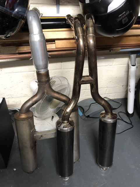
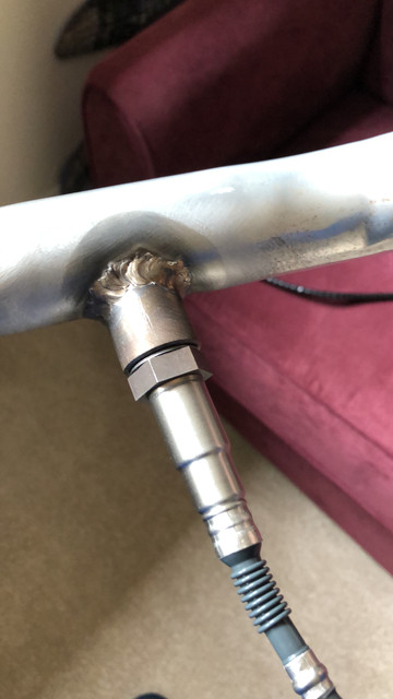
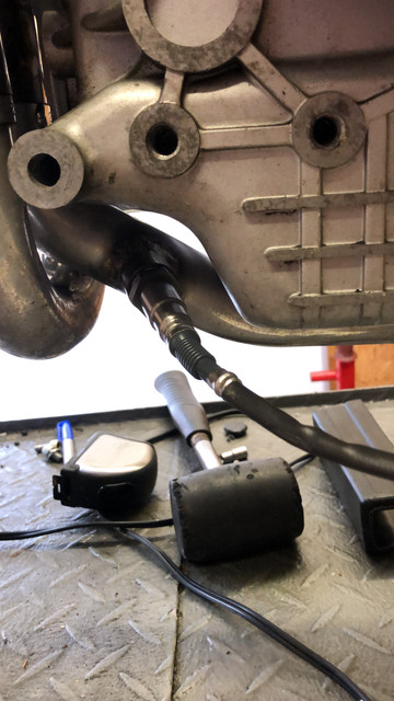
(the exhaust not the bike 🤣) waiting for the painter to finish painting the frame now 👀
Chad's always busy, I used RaceFit for the collector to save time - they are good and will do one offs - but Chad had to repair the collector I bought in the end, no biggy but it was stress cracked.
 
Thanks for the kind words, I've made many, many mistakes along the way here, but to me - that's how I learn - by testing all the possible ways that a particular task shouldn't be done, and what remains is the correct way to progress. Is that perseverance? - or just a learning process? :ROFLMAO:

'm not sure, without reading it all again, where you are with regards to your exhaust,
I'm all good on the exhaust, thanks. I imported a used two-into-two race system from Japan. In hindsight, it'd probably have been a similar cost to have one custom built, because the import costs were quite high. No matter though. It makes quite a racket, and not the pleasant boombastic bassy noise that the termi's on my SP5 (or my old 900SS) makes, so I need to be careful when I'm running it to avoid upsetting the neighbours ;)

Original system on the left, imported race system on the right. Saved several kilos over the original.


I'm lining up for a trip to the dyno at the end of this week to have a look at dialling in the Power Commnander.

Mike
 
What I noticed to my surprise is that the fuel pulses between the two cylinders are evenly spaced over 180 degrees (rather than 90/270 as we might expect for our V-twins). I've read the theory that suggests that the timing of the fuel pulse is not critical, because - like a carburettor, any fuel that is squirted when the valve is closed will naturally just gather in the port, waiting for the induction rush to pull it into the chamber, but I also understand that there are efficiency gains to be had to time the fuel pulses to the open valve.

I've been thinking over what you wrote there , and I agree , there's something odd .

Given how good ( and accurate ) modern injection / ignition systems have become , I can't think of any sensible reason why fuel
should ever be injected to closed inlet valve .
It's going to make the next combustion stroke over-rich , surely ?

Seems like throwing out the baby with the bathwater !

BTW - Keep up the great work and the fascinating posts .... really enjoying it ...... (y)
 
Back
Top